 |
 |
 |
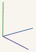
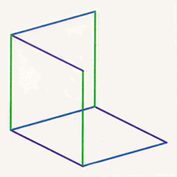
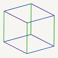
Left: The three edges at the vertex of the cube. Center: Completing three squares at the vertex of the cube. Right: Adding three edges to complete the cube.
One way to draw a cube is to build one out of sticks in three-dimensional space and hold it up in the sunlight. The edges of the cube cast shadow lines, which we can trace on a piece of paper. Such a procedure is awkward, but fortunately we do not have to trace the entire object, just enough to enable us to complete the drawing at our leisure. An easy way to do this is to sketch the images of three lines emanating from one corner of the cube and then complete the image by drawing three sets of four parallel lines.
Since parallel lines in space have images that are parallel lines in the plane, the image of a parallelogram is always a parallelogram (possibly degenerating into a line segment if the plane of the parallelogram is parallel to the rays of the sun). Thus if we know the images of two edges of a square, we can easily complete the image of the other two edges.
| ||||
Left: The three edges at the vertex of the cube. Center: Completing three squares at the vertex of the cube. Right: Adding three edges to complete the cube. |
Once we are given just the images of the edges from one corner, the process of completing a picture of a cube or a square is so straightforward that we can tell a computer how to do it. Even a small computer can draw several such pictures in a second, and it is now a standard demonstration on many machines to create a sequence of images of a cube, one after another, each differing only slightly from the previous one, to form a real-time animated cartoon. The information given to the computer is exactly equivalent to the position of three edges coming from a vertex of a cube. For the sake of the computer, this information is transmitted in numerical form rather than in pictures. The position of the vertex on the computer screen is given by a pair of numbers, and each of the endpoints of the three segments coming from the vertex is given by another number pair. Thus it is that eight numbers in a particular order give the precise information that allows the computer to display the three edges and then to figure out the location of all other edges of the cube and display them as well. We will treat these numerical descriptions further in Chapter 8.
The beautiful thing about this method of describing the views of a cube is that we never have to build the cube in the first place. We could use the same method to design a thousand-story building, and with some additional techniques, we could show the shape of the shadow it would cast at noon on a certain day at a certain latitude. How much more practical it is to use this abstract method than to build the object and trace the shadow!
A dramatic example of this method is the story of the Johnson Art Museum at Cornell University. Cornell University has been a pioneer in the application of computer graphics to architectural design, so it was natural for the campus planners to seek advice from people in the Program of Computer Graphics in the College of Architecture, Art, and Planning. The planners agreed that the multistory building should be erected close to the centers of activity. The precise location, however, depended on several factors, primarily the desire that the new structure literally not overshadow some of the traditional buildings or disrupt the balance of the Arts Quadrangle. The computer graphics experts under the direction of Donald Greenberg were able to answer these questions definitively. An interactive program gave the designers the option of selecting a site for the building, then seeing precisely how its presence affected the surrounding buildings. Armed with this information, the building committee made their selection confidently. An image from this project became the May, 1974 cover for Scientific American.
| Shadows of Hypercubes | ||
| Table of Contents | ||
| Drawing Shadows |