 |
When attached top to bottom and side to side, a four-by-four grid forms the polyhedral torus in the hypercube.
Up to this time, we have been discussing images made of lines, the easiest objects for a computer to draw. As technology improved, computers were able to fill in polygonal regions, creating images better resembling solid objects. But which polygonal faces should be filled in?
When we draw a picture of a solid cube, we want only to see three of the six square faces, the ones in front hiding the back faces from view. As the cube rotates, different squares will come into view, and color-coding, or markings as on dice, can help to identify which particular view appears at any given time. For a cube or a regular polyhedron, it is not difficult to decide which faces should be filled in, although this task becomes significantly more subtle when rendering images of more complicated objects in three-space.
For a hypercube, deciding which squares to fill in can be a problem. We could fill them all in, but then when we project the hypercube into three-space, we will see only those images lying on the outside of a solid polyhedron. The edges and faces inside the object will be hidden. In the central projection, for example, when the red cube is largest, we would not see the blue cube at all. We could make different faces emerge from within by rotating the hypercube, or with a more sophisticated computer, we could arrange for some of the faces to be transparent.
| ||
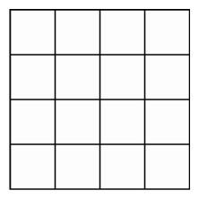
When attached top to bottom and side to side, a four-by-four grid forms the polyhedral torus in the hypercube. |
An easier technique is to leave out certain of the 24 square faces. Instead of displaying 3 squares at each edge, we can choose 16 of the squares so that there are 2 of them at each edge of the hypercube, forming a two-dimensional surface in four-dimensional space called a polyhedral torus. We may think of this torus as having a fold-out pattern in the plane consisting of a square subdivided into 16 smaller squares, together with a set of instructions for assembling it. The instructions are to fold the object up so that the top edge can be attached to the bottom, which we can do in three-dimensional space to form a square tube. But the instructions also require that we fold the original square so that the left edge can be attached to the right. Once again we can accomplish this instruction in three-dimensional space. But in three-dimensional space, it is impossible to carry out both instructions without stretching or tearing the original subdivided square. It is, however, possible to accomplish this in four-dimensional space since we can choose 16 squares from the hypercube so that there are 4 squares at each vertex and 2 squares at each edge.
When we use central projection to produce an image of the hypercube in three-dimensional space and then show the image on the computer screen, some of the 16 squares have images that are squares, whereas others will appear to be trapezoids or more complicated four-sided polygons. All these polygons will fit together to form a boxlike approximation of the familiar shape of a torus of revolution, obtained by revolving a circle around an axis. As we rotate the hypercube in four-dimensional space, the changing images of the polyhedral torus in four-space will appear to swim through each other. To gain a better appreciation of the importance of this torus in the study of objects in four-space, it is useful first to consider central projection as used in cartography.
| Stereographic Projection | ||
| Table of Contents | ||
| Animating the Hypercube |